 Business License

Method for Calibrating Thermocouples Using a Dry-Block Calibrator
Method for Calibrating Thermocouples Using a Dry-Block Calibrator
During operation, the hot junction of a thermocouple is subject to oxidation, corrosion, and high-temperature recrystallization of its constituent materials. These factors alter the thermocouple's characteristics, thereby introducing measurement errors. When the measurement error exceeds the permissible tolerance, the thermocouple must either be replaced entirely or repaired by cutting off the degraded section of the hot junction and re-welding it; in the latter case, the repaired thermocouple must undergo cleaning and successful verification before being put back into service.
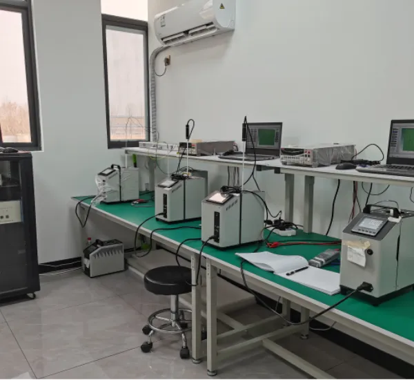
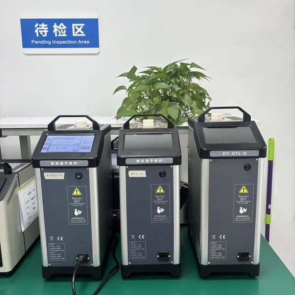
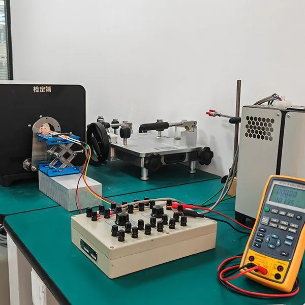
Typically, thermocouples are calibrated using either a portable dry-block calibrator or a dedicated thermocouple verification system. Within a verification system, thermocouples designed to measure temperatures below 300°C are calibrated using a constant-temperature bath, whereas those designed for temperatures exceeding 300°C require the use of a thermocouple calibration furnace.
Calibration furnaces (dry-block calibrators) require a specific temperature field profile within the chamber; ideally, they should feature a constant-temperature zone of approximately 300 mm in length, and the temperature fluctuation during readings must not exceed 0.2°C per minute. Typically, the temperature at the calibration point is adjusted by varying the voltage via an autotransformer, with precise control maintained through the use of thyristors and automatic temperature control instrumentation. Furthermore, the accuracy class of the associated potentiometer used for measurement must be no lower than Class 0.05.
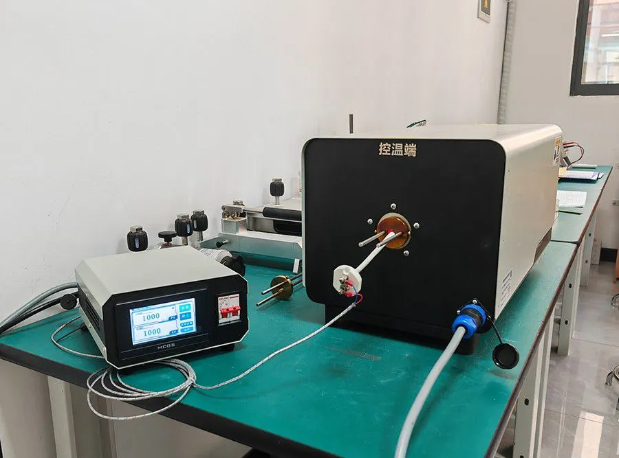
Procedure for Calibrating Thermocouples Using a Dry-Block Calibrator:
1. During calibration, place the hot junctions of both the thermocouple under test and the standard thermocouple (of Type S) into the calibration furnace to compare their respective measurement data. When verifying Type K or Type E thermocouples, they must be enclosed in quartz sheaths; subsequently, use nickel wire to bind them together with the thermocouple under test before inserting them into the isothermal zone of the calibration furnace. To ensure temperature uniformity between the hot junctions of the standard and test thermocouples, place the hot junctions of both devices into two separate holes within a solid nickel block; then, insert the nickel block into the isothermal zone of the furnace to conduct the verification.
2. Once the thermocouples have been inserted into the isothermal zone of the calibration furnace, the furnace opening must be sealed using asbestos rope. The standard insertion depth for thermocouples is typically 300 mm; for shorter thermocouples, this depth may be reduced appropriately, provided it remains no less than 150 mm. Position the cold junctions of the thermocouples within an ice-point bath to maintain a reference temperature of 0°C. When the furnace temperature reaches a range of ±10°C relative to the target calibration point—and provided the rate of temperature change does not exceed 0.2°C/min—measurements of the thermocouples' thermoelectric potential may be taken.
3. At each calibration temperature point, readings of the thermoelectric potential for both the standard thermocouple and the thermocouple under test (using the portable dry-block calibrator) must be recorded in a specific sequence: Calibration Point 1 → Point 2 → ... → Point n → Point 2 → Point 1. Furthermore, a minimum of four readings must be taken at each point. Subsequently, calculate the average value for each point, consult the relevant thermocouple reference table, and finally, determine the temperature error value by comparing the results.
Recently Posted
-
Principles of Blackbody Radiation Sources
April 14, 2026Principles of Blackbody Radiation SourcesAll objects emit electromagnetic radiation within a specific range of wavelengths. Radiat Read More
 -
Basic principles and temperature measurement errors of resistance temperature detectors (RTDs)
March 12, 2026Resistance temperature detectors (RTDs) are commonly used temperature sensing elements in the medium and low temperature range. Th Read More
 -
The main differences between metrological calibration and verification
March 12, 2026ISO 10012—1, "Quality assurance requirements for metrological testing equipment," defines "calibration" as: &q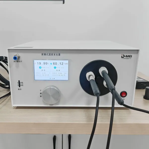 Read More
 -
Differences in the heat transfer medium of the Thermostatic bath
March 11, 2026The heat transfer medium in a constant temperature bath is also known as a heat carrier. Its main function is to conduct heat unde Read More

Contact Us
Recommended Products
-
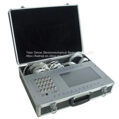
 DY-XJY01B Portable Multi-Channel Temperature and Humidity Field Testing SystemNegotiableMOQ: 1 Set
 -
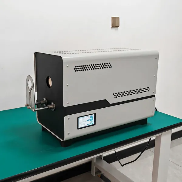
DY-JDL600 Thermocouple Calibration Furnace(300-1200c)NegotiableMOQ: 1 Piece
-
DY-JDL Horizontal Laboratory Temperature CalibrationNegotiableMOQ: 1 Piece
-
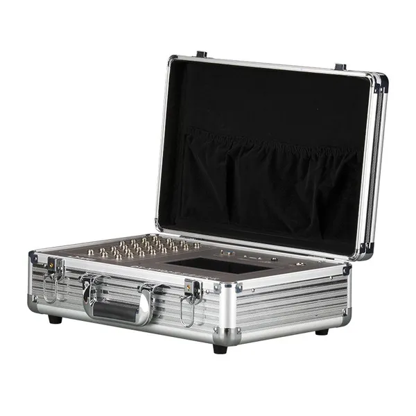
Portable Multi-Channel Temperature and Humidity Field Testing SystemNegotiableMOQ: 1 Set
-
Portable Multi-Channel Temperature and Humidity Field Testing SystemNegotiableMOQ: 1 Set
-
DY-JDL Laboratory Temperature Calibration / Thermocouple Calibration FurnaceNegotiableMOQ: 1 Piece
-
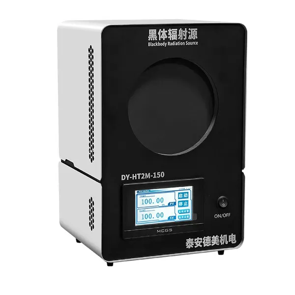
DY-HT2M-150 Medium Temperature Surface Source Blackbody Furnace, Radiation Surface 150mm (room Temperature +5-500℃)NegotiableMOQ: 1 Piece
-
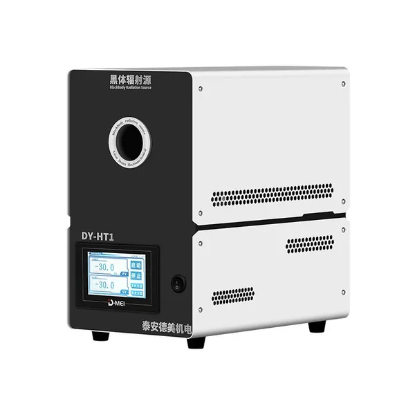
DY-HT1 Cavity Blackbody Radiation SourceNegotiableMOQ: 1 Set
-
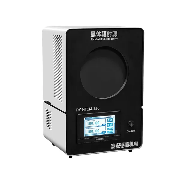
DY-HT1M-150 Low Temperature Surface Source Black Body Furnace, Radiation Surface 150mm (-20-100℃)Infrared Thermometer Calibration InstrumentNegotiableMOQ: 1 Piece
-
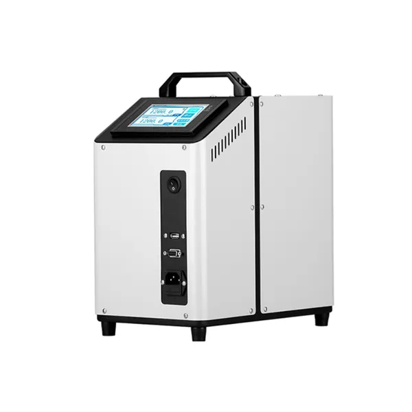
DY-GTLB Transformer Oil Level Thermometer Detection Device (-20℃-150℃)NegotiableMOQ: 1 Piece
-
DY-HT4-1 Blackbody Furnace/blackbody Radiation Source (800℃-1450℃)NegotiableMOQ: 1 Piece
-
DY-HT70MD Portable Intelligent Multi-faceted Blackbody Furnace (room Temperature +5°C~150℃)NegotiableMOQ: 1 Piece
-
DY-HT50M Portable Blackbody Furnace, Radiation Surface 50mm (room Temperature +5℃-500℃)/Infrared Thermometer Calibration InstrumentNegotiableMOQ: 1 Piece
-
DY-JDL Thermocouple Calibration FurnaceNegotiableMOQ: 1 Piece
-
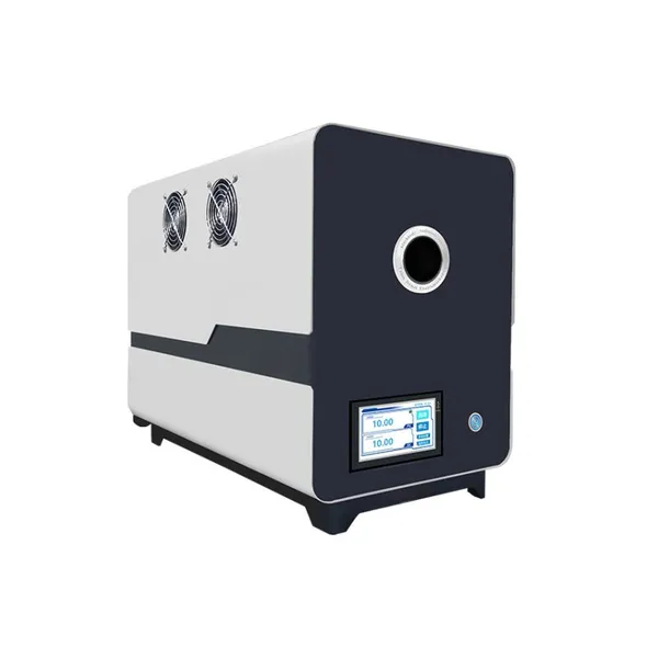
DY-JDL Laboratory Temperature Calibration Base Metal Thermocouple Calibration Furnace (300-1200c)NegotiableMOQ: 1 Piece
-
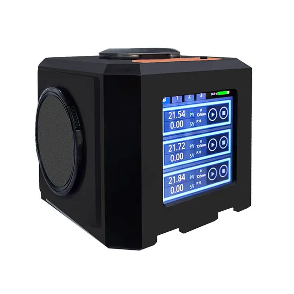
Thermocouple Cleaning and Annealing DeviceNegotiableMOQ: 1 Piece
-
Rapid Heating Blackbody Radiation Sources of Radiation Thermometry/ Standard Blackbody Stove(300-1200c)NegotiableMOQ: 1 Piece
-
High Precision Dry Block Temperature Calibrator/Dry Block Calibrator Definition(50-600c)NegotiableMOQ: 1 Piece
-
Thermocouple Annealing FurnaceNegotiableMOQ: 1 Piece
-
Rapid Heating Intelligent Dry Block Temperature Calibrator -120~40°CNegotiableMOQ: 1 Piece